Scan the WeChat code to contact us
Scan the WeChat code to contact us
Feel free to send us a email and we will reply to you as soon as possible.
Creating the future with heart and soul


Short answer: There is no single number for a railroad component. A bearing seat on a wheel axle might need ±0.025 mm, while a bolt hole in a fish plate can live happily at ±0.2 mm. The tolerance has to match what the part does, not what the drawing wants it to be.
The first thing I look for when someone asks me to review a tolerance is what the surface actually touches. A railroad component is rarely machined to one number. It is machined to several, and each surface earns the tolerance it gets.
A wheel hub bearing seat is one thing. The mounting holes for a brake hanger bracket are another. You do not give them the same number, and if you do, you are paying for something nobody asked for.
It sounds obvious. I have still watched people miss it on drawings more times than I can count.
The bearing seat is a functional surface. The railway wheel presses onto the axle, and that bore has to hold a press fit at speed, under load, with a shaft spinning inside it. Get the diameter a few hundredths of a millimetre off and the bearing either seizes or walks. That is where the tight numbers live: an axle journal bore might be called at H6 or H7, with roundness down around 0.005 mm and a surface finish of Ra 0.8 μm.
Now look at a fish plate bolt hole. It exists to pass a bolt through and let the rail ends work. A couple of tenths of a millimetre either way changes nothing about whether that joint stays tight. You would be paying for precision nobody needs.
That distinction, functional versus non-functional, is the whole game. And most of the tolerance arguments I have been pulled into over the years came down to somebody refusing to make that call.
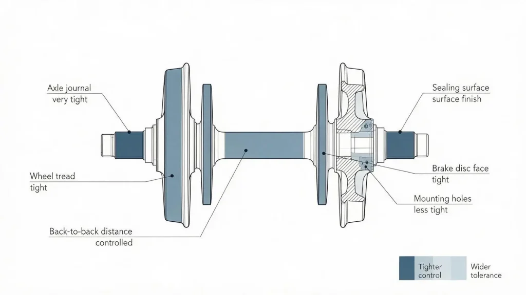
If you want a rough map of where tolerance matters on a railroad component, here is how I think about it. This is a starting point, not a universal specification, and every region’s standard will nudge these numbers.
| Surface or feature | Typical working range | Why it needs to be that tight |
| Axle journal / bearing bore | ±0.01 to ±0.05 mm | Press fit and running fit against bearings |
| Wheel tread profile | ±0.1 mm from reference | Controls wheel-rail contact and running stability |
| Back-to-back wheel distance | ±1 mm | Gauge compliance |
| Sealing / mating faces | Ra 0.8–1.6 μm finish | Leak and wear control |
| Disc brake friction surface | ±0.05 mm thickness, 0.02 mm parallelism | Judder and uneven wear |
| General bolt holes / mounting holes | ±0.1 to ±0.3 mm | Clearance for fasteners |
| Non-critical cast surfaces | ISO 2768 general class | Nothing functional touches here |
One thing worth noticing: the numbers are not evenly spaced. A disc brake face is held tighter than a mounting hole because the consequence of being wrong is different. That is the logic, not a rule.
On railway casting products, the story is a little different again. A casting comes out of the mould with its own draft, its own shrinkage, its own surface. You do not machine every surface of a casting, and you do not hold the unmachined ones to the same tolerance as the machined ones. The tight numbers only belong where a tool actually touched the metal.
Here is the thing nobody says out loud in the meeting. Tolerance is not free. It is paid for in machining time, in rejected parts, and in how many shops can even quote the job.
A general machining house can hold ±0.1 mm without breaking a sweat. Ask for ±0.02 mm and they start reaching for a different machine, a different fixture, and a CMM to prove it. Ask for ±0.005 mm and a lot of shops will quietly decline to bid, because they know what the scrap rate is going to look like.
Sometimes that cost is justified. A bearing journal on an axle cannot be sloppy.
But I would be cautious about a drawing that calls every dimension tight “just to be safe.” That is how you end up paying for a precision you cannot use, and it usually means whoever drew it did not think through which surfaces matter.
I would rather spend a little more on the two surfaces that actually carry load than spread the same money thin across twenty that do not. Oddly enough, the cheaper part is often the one where the engineer made that call properly.

This is where people get let down, and I understand why.
EN 13232 covers wheel and rail profile tolerances. AAR M-1001 and M-1003 cover wheel and wheelset requirements in North America. ISO 2768 gives you a general tolerance class for dimensions that have no explicit number on the drawing. ISO/TS 22163, the IRIS railway quality standard, tells you how the whole process should be managed.
None of them will tell you “the right tolerance for this part is X.” They give you a floor. They tell you the minimum you must meet to be compliant in a given region, or the default you fall back to when the drawing is silent.
The actual number comes from the function. The standard just makes sure you are not the only one deciding, and gives the inspector something to measure against.
When a customer in Europe specifies a wheel, they point at EN 13232. When a customer in North America specifies one, they point at AAR. Same part, different book, and the numbers are close but not identical.
That is why “which standard applies” is one of the first questions in any quote, not an afterthought.
A tolerance is a number on a dimension. But a part that measures in spec can still fail, and this is where a lot of inspection reports stop too early.
Two things ride along with the dimension and matter just as much: surface finish and geometric tolerance.
Surface finish is the texture. A shaft can hit its diameter dead on and still have a rough, torn surface that chews up a bearing in service. That is why a bearing journal carries a Ra 0.8 μm finish requirement on top of its ±0.025 mm diameter. One controls size, the other controls how the surface behaves under load.
Geometric tolerance is the shape and the relationship between features. A bore can be the right diameter but out of round. A wheel tread can be the right width but off centre relative to the axle. These do not show up as a simple ± number, but they are what actually decide whether the part runs true.
So when you read a drawing, do not just look at the biggest ± numbers. Look at the finish calls and the geometric frames. That is usually where the argument, and the cost, actually is.
If you are on the buying side, the tolerance is not really your problem to calculate. Your problem is to make sure the supplier can prove it. Here is the short list I would want before signing anything.
One check I run personally: the heat number. When I review a supplier’s documents, I do not look at the tensile strength alone. First I check whether the heat number on the certificate matches the marking on the wheel or the casting. If those two do not line up, I stop reading, because traceability is already broken.
A supplier who can hand over all of that without blinking is usually the one whose tolerances you can trust.
What is a typical tolerance for a machined railroad component?
It depends on the surface. Non-critical features often sit around ±0.1 to ±0.3 mm, while bearing seats, journals, and sealing faces run down to ±0.01 to ±0.05 mm. There is no single typical number, which is why the drawing should call each surface out separately.
Does a tighter tolerance always mean a better part?
Sometimes yes, sometimes no. A tight tolerance on a functional surface is usually worth it. The same tolerance on a mounting hole adds cost without adding performance. In practice, a tighter callout just means more machining time, more inspection, and a higher scrap risk, so it should be reserved for the surfaces that earn it.
Do railroad components need certification?
For most safety-relevant parts, yes. North America leans on AAR M-1001/M-1003 and FRA compliance, while Europe points to EN standards and ISO/TS 22163 (IRIS). Always ask which standard applies to the region the part will run in, and request the full documentation rather than a blanket “certified” claim.
Can machining replace a cast or forged railroad component?
For many parts, machining is the final precision pass on a cast or forged blank rather than a full replacement. The casting or forging gives you the grain flow and the bulk shape; the machining gives you the finished functional surfaces. A few parts are machined from solid bar or plate where the volume is low enough to make that practical.
Why does the same wheel have different tolerances in different regions?
Because the governing standards differ. EN 13232 and AAR M-1001 both define wheel and wheelset requirements, but the exact numbers are close rather than identical. A part built to one may still need a review against the other before it can run in that region. This is a standards question, not a quality question.
Should a non-functional surface ever get a tight tolerance?
Not usually, and I would push back on it. Tight tolerances on surfaces nothing touches raise the cost of the whole part and can even create manufacturing problems for no benefit. The exception is when a feature is a datum, or a future machined surface, where its own accuracy sets up the accuracy of something else.
A railroad component may look like one of the simplest things a shop machines, but the tolerance callouts are where the engineering actually happens. The trick is not to make everything tight. It is to know which two or three surfaces carry the load, hold those properly, and stop paying for precision on the rest.
Whether you are specifying a new railway wheel, reviewing a railway casting product, or replacing worn fasteners, the number that matters is the one tied to what the part does. If you would like a second set of eyes on a drawing, we are glad to look at it before you commit.
At Luoyang Fonyo Heavy Industries Co., Ltd., we manufacture railway wheels, railway casting products, fish plates, fish bolts, elastic rail clips, and rail pads. Send us your drawing and the applicable standard, and our engineering team will review the tolerances with you before quotation.