WeChat 코드를 스캔하여 문의하세요
WeChat 코드를 스캔하여 문의하세요
이메일을 보내주시면 최대한 빨리 답변해 드리겠습니다..
마음과 영혼을 다해 미래를 창조하다


1.1 Fault Phenomenon:
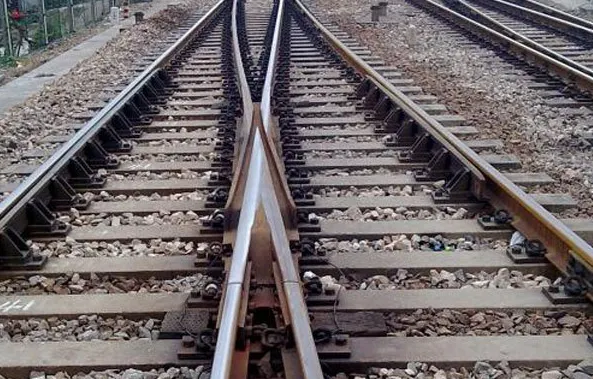
When the operator issues a conversion command in the control room, the switch moves slowly and with difficulty, or even gets completely stuck, and the power system emits abnormal sounds or alarms due to overload.
Root Cause Analysis:
The fundamental cause is usually the “lack of lubrication” 또는 “inflexibility” of the mechanical transmission parts.
1.2 Contamination and Scaling of the Slide Bed Plate:
This is the most common cause. Coal dust, sand, rust, and other foreign substances form a hard layer between the slide bed plate and the bottom of the switch blade, generating significant frictional resistance.
Switch Blade Creep: Due to temperature changes or longitudinal forces, the switch blade undergoes excessive displacement, causing it to jam against the connecting rod or locking device.
1.3 Loose or Worn Components:
The loosening or wear of various connecting rods and bolts alters the geometric dimensions of the transmission mechanism, leading to poor operation.
1.4 Efficient Solutions:
Cleaning and Lubrication: This is far from simply “applying some oil”. 첫 번째, all dirt and rust on the slide bed plate must be thoroughly removed using professional tools (such as steel scrapers and wire brushes) until the metal surface is exposed. 그 다음에, apply high-performance switch-specific lubricating grease designed for heavy-duty conditions to ensure the lubricant penetrates the friction surfaces rather than just covering the surface.
Precise Adjustment and Anti-Creep Locking: Check and retighten all connection components. For switch blade creep, use a hydraulic switch adjuster to precisely reset it and enhance the anti-creep locking devices on the track, such as adding more creepers on the outside of the base rail to fundamentally suppress displacement.
Establish a Periodic “Health Check” System: Make the cleaning, lubrication, and tightness inspection of switches an absolute priority in daily maintenance. Based on traffic volume and environmental harshness, set a maintenance cycle that is stricter than the standard.
2.1 Fault Phenomenon:
After the switch is converted to position, the control room displays no indication, preventing the signal system from confirming the switch’s status and triggering a safety interlock, interrupting train operation.
Root Cause Analysis:
This is due to the indication detection device’s failure to accurately sense the actual position of the switch blade.
2.2 Foreign Object in the Indication Rod Notch:
Stones, 얼음, and other objects fall into the notch of the indicator’s detection rod, preventing the indication rod from falling normally.
2.3 Excessive Installation Gap:
The gap between the indication rod and the detection rod changes due to mechanical vibration, exceeding the allowable range, causing the indication circuit to fail to connect.
2.4 External Environmental Impact:
Heavy rain or melting snow causes water to enter the indication device, resulting in electrical short circuits or oxidation.
2.5 Efficient Solutions:
“Microscopic” Inspection and Gap Calibration: Like a surgeon, use a feeler gauge to precisely measure the gap between the indication rod and the detection rod and adjust it strictly in accordance with technical specifications. During daily inspections, use a flashlight to carefully check the notch area and remove any tiny foreign objects.
Enhanced Sealing and Waterproofing: Regularly replace the sealing gaskets at the connection ports and box covers of the indication device to ensure their elasticity. Conduct special waterproof checks before the rainy season or snowy weather.
Introduce Online Monitoring: For critical switches, install an online monitoring system for the indication circuit to record the voltage and current curves in real time. Once there is a slight fluctuation, it can issue a warning, 예측 유지 관리 지원.
3.1 Fault Phenomenon:
After conversion, there is a visible gap between the tip of the switch blade and the base rail. When a train passes, the wheels cause a severe impact on the switch blade, producing a loud “clanging” sound and accelerating its damage.
Root Cause Analysis:
3.2 Misalignment of the Frame Dimensions: The core geometric dimensions, such as the gauge and offset in the switch area, exceed the limit due to long-term impact, disrupting the overall frame structure. 3.3 Insufficient or Excessive Conversion Force: Improper adjustment of the turnout machine’s output force, or bending and deformation of the tie rods/connector bars.
3.3 Sliding Bed Plate Welding Failure or Lifting: The sliding bed plates supporting the switch rail become detached from the weld or become loose from the ties, causing the switch rail to sink under force and fail to smoothly align with the base rail.
3.4 Efficient Solutions:
Restore the Frame: Use tools such as track gauges and offset gauges to conduct a comprehensive measurement of the turnout. Adjust the gauge blocks and nylon seats to restore the gauge and offset to within the millimeter-level range of the design precision. This is a prerequisite for resolving the issue of poor alignment.
Adjust Conversion Force and Travel: With the assistance of professional instruments, precisely adjust the travel of the turnout machine’s action rod and the locking force to ensure that the force is sufficient to position the switch rail accurately without being excessive and causing damage to components.
Eliminate “Floating Points”: Conduct a tapping inspection of all sliding bed plates. If a hollow sound is heard, it indicates a “lifting plate”. Immediate track lifting and tamping or compacting the ballast under the ties should be carried out to ensure uniform support throughout the line. For weld failures, the old welds must be completely removed and re-welded.
4.1 Fault Phenomenon:
The guiding working surfaces of the switch rail and base rail, as well as the throat area of the wing rail, show signs of metal being squeezed, piled up, or side-worn, with the rail head profile deformed.
Deep Analysis of the Cause:
This is an inevitable result of the hard contact between the wheel flange and the rail, but it can deteriorate rapidly under certain conditions.
Total weight: This is the fundamental factor. The greater the volume of traffic, the faster the wear.
4.2 Poor track geometry: As mentioned earlier, poor alignment and gauge will intensify the impact and sliding friction between the wheel and rail.
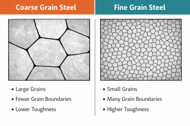
4.3 Material and heat treatment process: The initial hardness, toughness and uniformity of heat treatment of the rail material directly determine its wear resistance.
4.4 Efficient solutions:
“Proactive intervention” profile grinding: Do not wait until the wear exceeds the standard to replace. Regularly use turnout grinding machines to perform preventive profile restoration on worn areas, reshape the ideal profile of the rail, keep the wheel-rail contact point in the best position, and achieve a smooth transition, fundamentally reducing the impact force.
Use high-quality alloy rails: In severely worn areas (such as the switch rail and guard rail), replace with turnout components made of high-strength alloy steel (such as high manganese steel) and specially heat-treated. These components have a higher surface hardness and a wear resistance 2-3 times that of ordinary high-carbon rails, significantly extending their service life.
Precision lubrication: Install high-performance roller lubrication devices on the side of the basic rail of the guide curve at the front end of the switch rail to directly reduce wear by lowering the friction coefficient.
5.1 Fault Phenomenon:
Fasteners such as spring clips, gauge plates, 볼트, and switch sleeper connecting bolts become loose, break, or fail.
5.2 In-depth Cause Analysis:
Under continuous vibration and impact loads, any connection may fatigue.
5.3 Vibration and Impact: Periodic impacts of train wheels on rail joints and irregularities.
5.4 Insufficient Pre-tightening Force: Installation without reaching the specified torque or inadequate anti-loosening measures (such as ineffective spring washers).
5.5 Thread Corrosion: In damp and saline-alkali environments, thread pairs rust and “seize up”, reducing or even eliminating the pre-tightening force.
5.5Efficient Solutions:
“Fixed Torque” Operation Method: Equip maintenance teams with torque wrenches and enforce their use to ensure that every bolt is tightened to the design torque and record it.
Periodic Retightening and Replacement: Conduct three comprehensive retightenings in the first month, third month, and half a year after the new turnout is put into use. Thereafter, include it as a key point in quarterly inspections. For critical bolts, even if no abnormalities are observed, they should be replaced preventively at regular intervals (such as every two years).
Adopt New Anti-loosening and Anti-corrosion Technologies: Promote the use of bolts coated with long-lasting anti-rust grease, or use self-locking anti-loosening fastening systems such as shear bolts and self-locking threads to enhance structural reliability.
뤄양포뇨중공업(Luoyang Fonyo Heavy Industries), 주식회사, 1998년에 설립된 철도 주조 부품 제조업체입니다. 저희 공장 부지는 72,600㎡입니다., 이상으로 300 직원, 32 기술자, 포함 5 수석 엔지니어, 11 보조 엔지니어, 그리고 16 기술자. 우리의 생산 능력은 30,000 연간 톤. 현재, 우리는 주로 주조물을 생산하고 있습니다, 가공, 기관차 조립 및 조립, 철도 차량, 고속 열차, 광산 장비,풍력,등.
우리는 CRRC에 철도 부품을 공급하고 있습니다.(이상 포함 20 CRRC의 지사 및 자회사),Gemac 엔지니어링 기계,삼니그룹, 중공업,등. 우리의 제품은 러시아로 수출되었습니다, 미국, 독일, 아르헨티나, 일본, 프랑스, 남아프리카,이탈리아와 전 세계의 다른 나라들.