Scannez le code WeChat pour nous contacter
Scannez le code WeChat pour nous contacter
N'hésitez pas à nous envoyer un email et nous vous répondrons dans les plus brefs délais.
Créer l'avenir avec cœur et âme


Quand les ingénieurs parlent de fabrication de précision, one of the first topics that comes up is tolérances d'usinage. Machining tolerances define how much a dimension of a part can vary while still ensuring the part functions correctly. The tolerance should be properly machined. otherwise even a small deviation can cause assembly problems, vibration, or premature wear.
Beyond dimensional tolerances, engineering drawings often specify other key requirements, including geometric accuracy, état de surface, and runout. Understanding these requirements is crucial for engineers, manufacturers, and quality control teams alike.
Dans notre fonderie, we manufacture precision machined components for railway systems, y compris custom roues de chemin de fer, pièces moulées, and heavy-duty mechanical components selon les dessins du client. While in this article, we’ll break down the most common machining tolerances and explain what they really mean in real-world engineering, with examples that illustrate why these specifications matter.
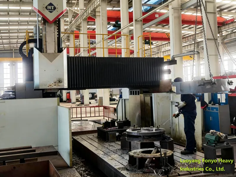
Dimensional tolerances are the most basic and commonly specified machining requirement. They define the acceptable range for a part’s size. Par exemple, if a shaft diameter is given as:
Ø50 ±0.02 mm
The actual part must fall between 49.98 mm and 50.02 mm.
Perfect dimensions are impossible to achieve in manufacturing due to tool wear, machine vibration, and material response. So engineers use the ISO system of limits and fits standards to define tolerances for holes and shafts, ensuring proper fits and functionality.
Practical example: A shaft designed to fit into a bearing must have tight tolerances perfectly. If too large, the bearing won’t fit; too small, and the bearing may spin freely, causing damage. By specifying proper tolérances d'usinage, engineers ensure reliable assembly and performance.

Even if a part has the correct dimensions, it may still fail if its shape or alignment is off. Geometric tolerances control the form, orientation, and location of features. They are standardized in OIN 1101.
Common geometric tolerances include:
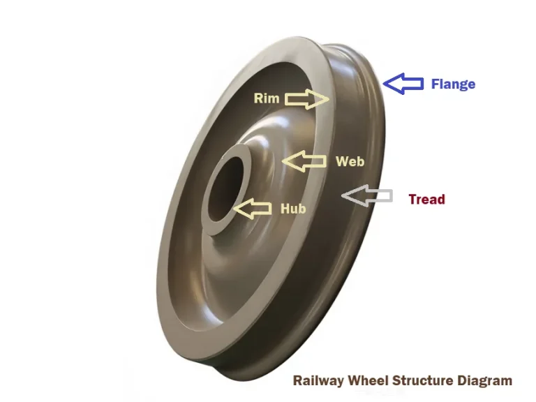
Example in practice: In a bearing seat, flatness and cylindricity are critical. Even a 0.02 mm deviation can cause uneven stress distribution, leading to premature bearing failure. In our experience with railway wheel hubs, controlling geometric tolerances ensures the wheel rotates smoothly and safely.
Runout is a critical tolerance for rotating components such as roues de chemin de fer. It measures how much a surface deviates from perfect rotation.
Two common types:
Runout control is very important for shafts, gear assemblies, flanges, and railway wheels. Excessive runout can cause vibration, bruit, and uneven loading.
Practical tip: In our wheel assembly operations, we typically control runout to within 0.05 mm for all critical rotational surfaces. This ensures smooth rotation at high speeds and prevents uneven wear.
Surface finish refers to the microscopic texture of a machined surface. It is typically measured as Râ, according to OIN 1302.
| Râ 12.5 | Usinage grossier |
| Râ 6.3 | Standard turning |
| Râ 3.2 | Finish turning |
| Râ 1.6 | Grinding |
Surface finish affects friction, résistance à l'usure, sealing performance, et durée de vie en fatigue. Par exemple, a sealing flange with rough edges may leak, while a smoother surface ensures proper sealing.
Case study: In railway brake systems, controlling surface finish on contact pads and wheel rims is essential. A small increase in roughness can increase wear by up to 15%, affecting both safety and maintenance costs.
Different processes achieve different levels of accuracy:
| CNC Turning | ±0.01 – ±0.05 mm |
| Fraisage CNC | ±0.02 – ±0.05 mm |
| Grinding | ±0.002 – ±0.01 mm |
| Forage | ±0.05 – ±0.1 mm |
| Ennuyeux | ±0.01 – ±0.02 mm |
Grinding is usually reserved for surfaces requiring extremely tight tolerances, such as bearing seats, arbres, or sealing surfaces.
Tip from experience: For complex railway wheel hubs, we often combine turning with finish grinding to achieve both dimensional and geometric accuracy.
For general mechanical parts, OIN 2768 defines standard tolerances if no specific tolerance is given:
| 0–30 mm | ±0.1 mm |
| 30–120 mm | ±0.15 mm |
| 120–400 mm | ±0.2 mm |
| 400–1000 mm | ±0.3 mm |
Critical features, like bearing interfaces or sealing surfaces, usually require tighter tolerances than general dimensions.
It’s important to understand the difference:
Exemple: A shaft may meet diameter tolerance but have a rough surface that increases friction or wears out a bearing faster. Engineers must often balance machining tolerance and surface finish based on functional requirements.
Here’s a quick reference of tolerances often used in engineering design:
| Shaft diameters | ±0.01 – ±0.05 mm |
| Trous | ±0.02 – ±0.05 mm |
| Flat surfaces | 0.01 – 0.05 mm |
| Rotating surfaces | ±0.02 mm |
Pro tip: Always check whether the tolerance applies to functional surfaces ou non-critical dimensions. Overly tight tolerances increase cost without benefit.
Proper tolerances ensure components fit correctly and perform reliably.
Exemple: A railway axle with a slightly oversized shaft may jam in the bearing, while a slightly undersized shaft can lead to vibration and wear. Proper tolerances prevent these problems.
In heavy machinery and energy systems, controlling machining tolerances reduces maintenance costs and improves safety.
Understanding tolérances d'usinage is essential for designing reliable mechanical components and ensuring successful manufacturing.
Machining is much more than simply cutting metal to a certain size.
Every machined part must meet a combination of requirements, including dimensional tolerances, geometric accuracy, état de surface, and alignment. These specifications ensure that components fit correctly, operate smoothly, and perform reliably in demanding environments. In industries such as railways, matériel lourd, and energy systems, precision machining plays a critical role in ensuring long-term safety and durability.
At our company, Luoyang Fonyo Heavy Industries Co., Ltd.we manufacture custom machined components, pièces ferroviaires, and forged products according to customer drawings and technical specifications.
Learn more about our capabilities at:
www.railwaypart.com