WeChat 코드를 스캔하여 문의하세요
WeChat 코드를 스캔하여 문의하세요
이메일을 보내주시면 최대한 빨리 답변해 드리겠습니다..
마음과 영혼을 다해 미래를 창조하다


Imagine a 10,000-ton heavy-haul train speeding through a curve at 80 시간당 킬로미터. Between the wheels and the rails, a fierce battle of huge centrifugal forces and complex guiding forces is taking place. What ensures that the wheelsets – 그만큼 “피트” of this steel behemoth – can flexibly follow the track’s direction without losing control and swerving or experiencing severe hunting? The core answer lies in a sophisticated and crucial system on the bogie: axle box guidance. It is far from a simple “fixing” but rather an art of “intelligent restraint” that grants the wheelsets controlled degrees of freedom. 오늘, we will delve into how this invisible “hand” shapes the steady gait of rail vehicles and explore its mainstream “restraint approaches”.
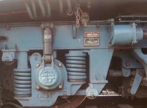
The core task of axle box guidance is to manage the degrees of freedom of the wheelset relative to the bogie frame. When the wheelset runs on the rail, there are theoretically six degrees of freedom: three translations (vertical, 옆쪽, and longitudinal) and three rotations (roll, pitch, and yaw). The goal of the axle box guidance device is:
Necessary Restraint:
Strictly control lateral displacement: Prevent excessive lateral movement of the wheelset during straight-line operation and ensure a safe gap between the wheel flange and the rail during curve operation to avoid derailment risks. This is the primary safety goal of guidance.
Moderate Restraint: Limit the yaw movement (rotation around the vertical axis, Z-axis) of the wheelset. Excessive free yaw angle is the main factor that triggers vehicle hunting instability (a dangerous periodic lateral oscillation).
Managing longitudinal displacement (traction/braking force transmission): Ensure that the wheelset can effectively transmit traction and braking forces to the frame while buffering longitudinal impacts.
Necessary release:
Allow vertical movement: This is the basis for the first-stage suspension function. The wheelset needs to be able to jump up and down relative to the frame to buffer the impact from the track.
Allow moderate roll: Adapt to the unevenness of the track and the height difference between the inner and outer rails when passing through curves.
그러므로, an excellent axle box positioning design is to find a delicate balance between being “too tight” (which leads to deterioration of dynamic performance and increased wheel-rail wear) and being “too loose” (which endangers operational stability). Different positioning forms are different “balance solutions” provided by engineers for different vehicle types, speeds, loads, and cost requirements.
Guide frame positioning: The classic and reliable representative of “hard constraints.”
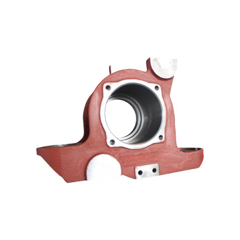
Structural principle: This is the most traditional and structurally intuitive positioning method, especially widely used in the classic three-piece bogie (such as the mainstream K series in China). The sides or outer sides of the axle box body (usually a cast steel part) are designed with protruding guide slots (or called guide frames). The side frame of the bogie is cast with matching guide platforms (called guide frame seats). The guide slots of the axle box are “embedded” in the guide platforms of the side frame, and there is a certain gap between them in the lateral and longitudinal directions (usually a few millimeters).
Constraint mechanism:
Lateral constraint: When the wheelset attempts to move laterally, the sides of the axle box guide slots will contact the sides of the side frame guide platforms, preventing further lateral movement through rigid contact. The size of the constraint gap directly affects the lateral positioning stiffness of the wheelset. A smaller gap results in greater stiffness and better stability but may increase wheel flange wear when passing through curves; a larger gap has the opposite effect.
Longitudinal constraint: 비슷하게, it relies on the contact between the front and rear ends of the guide slots and guide platforms to transmit traction and braking forces and limit excessive longitudinal movement of the wheelset (the constraint of the hunting motion is mainly achieved through this as well).
Characteristics and application:
장점: Simple structure, sturdy, 믿을 수 있는, low cost, relatively easy to manufacture and maintain. It is extremely widely used in heavy-duty, medium and low-speed freight cars and has been well-tested.
Engineering wisdom: Although simple, the design of the gap, the wear-resistant treatment of the contact surfaces of the guide slots and guide platforms (such as installing wear plates), and the lubrication method (using oil-impregnated nylon wear plates) all contain rich engineering experience, aiming to balance wear life and dynamic performance.
Rod (or link) positioning: 그만큼 “elastic bond” of modern high-speed
Structural principle: This is the mainstream positioning method for modern integral frame bogies (승용차, EMU, and some high-speed/express freight cars). The axle box is directly connected to the bogie frame through 1-2 rigid or elastic links (막대). The ends of the rods are usually connected with elastic joints (such as rubber-metal composite bushings and ball joints), allowing the rods to have a certain angular displacement in space.
Constraint mechanism:
The core of elastic constraint: The rods themselves mainly bear tensile and compressive forces. Their arrangement determines the direction of the constraint.
Single rod (such as a Z-shaped arrangement): Commonly seen in some designs, it can provide both longitudinal and lateral constraints, but the coupling of stiffness is relatively complex.
Double rods (eight-shaped or human-shaped arrangement): The most common. Two rods are connected in a V-shape (eight-shaped) or inverted V-shape (human-shaped) between the top of the axle box and the frame. This arrangement ingeniously decouples stiffness and damping:
High longitudinal stiffness: The two rods are almost parallel in the longitudinal direction, enabling efficient transmission of traction/braking forces.
Moderate and adjustable lateral stiffness: The size of the V-shaped angle and the stiffness of the rods themselves (including the stiffness of the elastic joints) jointly determine the lateral constraint stiffness. The smaller the angle, the greater the lateral stiffness. Engineers can precisely “tune” the vehicle’s stability and curve passing performance by carefully designing the angle and joint stiffness. Primary suspension separation: The vertical load is borne by independent axle box springs (coil springs, rubber springs) or rubber stacks on the top of the axle box, functionally separated from the locating tie rods.
Characteristics and applications:
장점:
Minimal wear or no wear: Elastic joints eliminate sliding friction between metals, significantly reducing maintenance workload and enhancing reliability.
Precise and controllable positioning parameters: Parameters such as tie rod length, angle, and joint stiffness can be precisely designed and adjusted to achieve the best longitudinal and lateral stiffness matching, optimizing vehicle dynamics performance (high-speed stability, curve negotiation, wheel-rail wear).
Additional damping provided: The elastic joints (especially rubber bushings) themselves can provide a certain amount of damping, which helps suppress vibrations. Sometimes, vertical or lateral hydraulic shock absorbers (primary shock absorbers) are integrated into the tie rod system.
Suitable for high-speed operation: It is the preferred choice for high-speed passenger cars, EMU, and high-end freight cars.
Disadvantages: The structure is relatively complex, with high manufacturing costs and extremely high requirements for the performance and durability of elastic components. Rubber bushings have an aging problem and need to be inspected and replaced regularly.
Fine-tuning of the “elastic link”: The geometric arrangement of the pull rod, the axial/radial stiffness of the joints, and even the bending stiffness of the pull rod itself are all “knobs” for engineers to optimize dynamics, reflecting the refinement of modern vehicle design.
Rubber spring (stack) positioning: 에이 “one-stop solution” that is soft yet firm
Structural principle: This is a highly integrated solution that combines the primary suspension and axle box positioning functions. It uses large-sized rubber-metal composite springs (rubber stacks) directly installed on the top of the axle box (or between the axle box and the frame), replacing traditional coil springs and independent positioning rods.
Constraint mechanism:
Multi-functional integration: The rubber stack provides vertical elastic support (primary suspension function). 동시에, relying on the shear stiffness and compressive stiffness of the rubber material itself, it provides the required elastic constraint forces in the lateral and longitudinal directions. Rubber is an excellent material with adjustable stiffness in three directions.
Anisotropic design: Engineers can change the internal structure of the rubber stack (such as the shape and angle of the metal separator, the thickness and hardness distribution of the rubber layer) to make it exhibit different stiffness characteristics in the vertical, 옆쪽, and longitudinal directions (i.e., anisotropy). 예를 들어, it can be designed to have a smaller vertical stiffness (to ensure a buffering effect) and larger lateral and longitudinal stiffness (to ensure stability).
Characteristics and application:
장점:
Extremely simple and compact structure: Fewer parts, lighter weight, easy to install and maintain.
No wear, no lubrication: Rubber elastic elements are reliable and have low maintenance costs.
탁월한 진동 및 소음 감소 성능: Rubber has high internal resistance and can effectively absorb high-frequency vibrations and noise, significantly improving ride comfort.
Provides three-directional elastic constraints: The integrated design simplifies dynamic matching.
Disadvantages:
Rubber aging: Sensitive to temperature, ozone, and oil stains, it has an aging problem, and performance will gradually decline over time, requiring regular inspection and replacement.
Relatively limited load-bearing capacity: Less mature and common in applications with large axle loads (such as heavy-duty freight cars) compared to metal springs or pull rod positioning.
Nonlinear stiffness and temperature sensitivity: Rubber stiffness varies with deformation and temperature, and comprehensive design considerations are needed.
Application scenarios: Widely used in urban rail transit vehicles (지하철, light rails), medium and low-speed passenger cars, some trailer cars of EMUs, and special freight cars with high requirements for comfort and low maintenance. Its advantages of being quiet and maintenance-free are particularly prominent in urban transportation with frequent starts and stops and sensitive environments.
그만큼 “one-stop solution” of harmony: Rubber stack positioning demonstrates the wisdom of high integration in engineering and material application, achieving multiple functions through a single component and pursuing harmony and efficiency in the overall system.
Choosing which type of axle box positioning is a key decision in vehicle design and requires comprehensive consideration:
Operating speed: High-speed vehicles (>120 km/h) prefer pull rod type or high-performance rubber stack type; for medium and low-speed freight cars, guide frame type still has cost advantages.
Load and axle load: Guide frame type and pull rod type are more mature in heavy-duty applications; rubber stack performs well under medium axle loads.
Operating environment and maintenance capability: Rubber stack is preferred in metro and light rail for its maintenance-free feature; guide frame type is acceptable for freight cars in areas with dense maintenance points.
Cost control: Guide frame type has the lowest manufacturing cost; pull rod type and high-performance rubber stack type have higher costs.
Dynamic performance goals: Different focuses on stability, comfort, curve passing ability, and wheel-rail wear require corresponding stiffness characteristics from the positioning form.
Axle box positioning, although not as eye-catching as the wheel rail, is the “behind-the-scenes director” of the dynamic performance of rail vehicles. From the robust and reliable guide frame type to the precise and adjustable pull rod type and the flexible and quiet rubber stack type, each form embodies the wisdom of engineers in seeking the best balance between “constraint” 그리고 “release”. They are like custom-made dance shoes or stabilizers for the “iron feet” of the wheels, ensuring that the steel dragon can take safe, stable and efficient steps whether it races across vast plains or winds through towering mountains. Understanding the operating principle of these “invisible hands” is the technical cornerstone for us to control the steel dragon and travel thousands of miles. Their silent guardianship and precise control underpin every smooth arrival at the station.
뤄양포뇨중공업(Luoyang Fonyo Heavy Industries), 주식회사, 1998년에 설립된 철도 주조 부품 제조업체입니다.. 우리 공장의 면적은 72,600㎡입니다., 이상으로 300 직원, 32 기술자, 포함 5 수석 엔지니어, 11 보조 엔지니어, 그리고 16 기술자. 우리의 생산 능력은 30,000 연간 톤. 현재, 우리는 주로 주조물을 생산하고 있습니다, 가공, 기관차 조립 및 조립, 철도 차량, 고속 열차, 광산 장비, 풍력, 등.
우리는 CRRC에 철도 부품을 공급하고 있습니다.(이상 포함 20 CRRC의 지사 및 자회사), Gemac 엔지니어링 기계, 삼니그룹, 중공업, 등. 우리의 제품은 러시아로 수출되었습니다, 미국, 독일, 아르헨티나, 일본, 프랑스, 남아프리카, 이탈리아와 전 세계의 다른 나라들.
연락처 정보:
이메일:[email protected]
이동하는:008615515321683