Scan the WeChat code to contact us
Scan the WeChat code to contact us
Feel free to send us a massage and we will reply to you as soon as possible.
Creating the future with heart and soul

As the core carrier of urban rail transit, the technical integration and operational reliability of the subway vehicle system directly determine the operational efficiency. This article starts from the four major modules of bogie, traction system, braking system and TCMS system, and deeply analyzes their technical configuration and coordination mechanism.
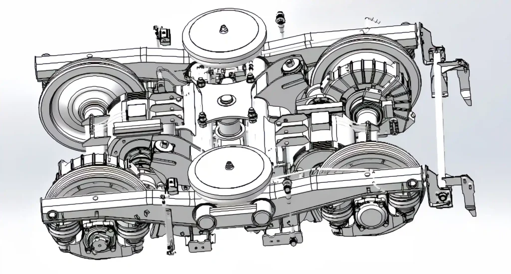
1. Bogie system: load-bearing and dynamic core
As the vehicle running part, the bogie undertakes the dual functions of load transmission and dynamic performance optimization. Its core configuration includes:
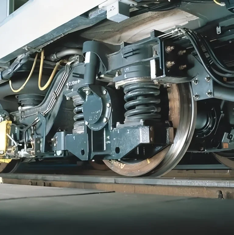
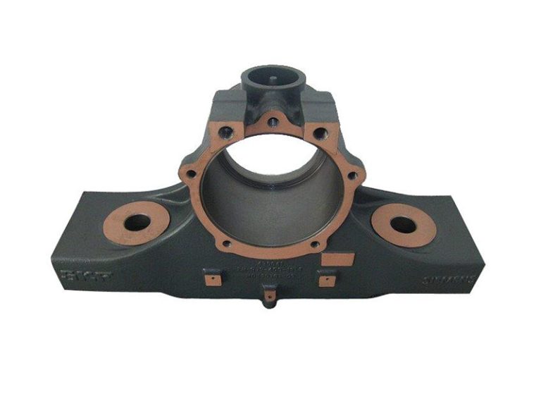
Frame structure: It adopts an H-shaped double-beam welded frame, and the main load-bearing components are made of S275J2G3 steel plates of EN10025 standard, with a fatigue life of more than 30 years. The side beam integrates the air spring mounting seat and the lateral shock absorber interface, and the cross beam is equipped with a motor hanger, a gearbox hanger and a traction rod seat to realize the modular integration of the power unit.
Suspension system: The first suspension adopts a combination of double-coil steel springs and rubber nodes, with a vertical stiffness of 2.5-3.5MN/m and a lateral positioning stiffness of 8-12MN/m; the second suspension is equipped with air springs with a stiffness of 0.2-0.3MN/m, combined with an anti-roll torsion bar device to suppress the body roll angular acceleration to within 0.3rad/s².
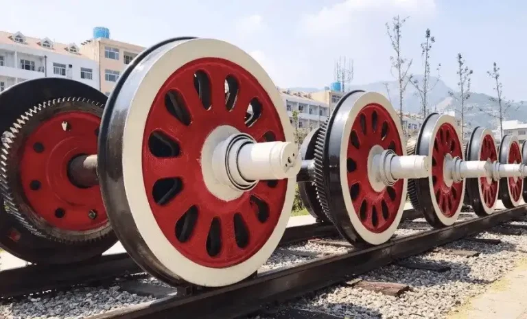
Wheelset and drive: The power wheelset integrates the traction motor and gearbox, and the non-power wheelset adopts a lightweight hollow axle. The axle box bearing uses UIC standard tapered roller sealed bearings, and cooperates with plastic steel cages to achieve a maintenance-free cycle of 1.2 million kilometers.
Dynamic optimization: The load is adaptively adjusted through the air spring height valve, and the anti-snaking shock absorber and lateral buffer are used to reduce the wheel-rail lateral force by 15% when the vehicle passes through the curve, and the derailment coefficient is controlled within 0.8.
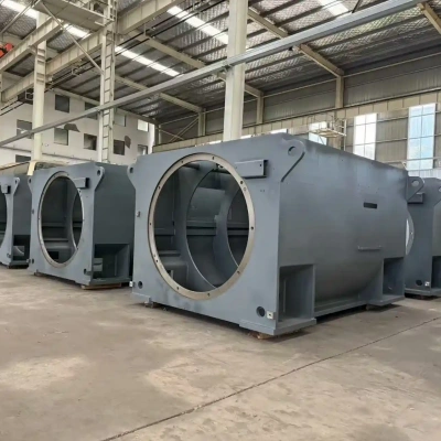
2. Traction system: the energy center of power and electric braking
The traction system realizes efficient conversion of electrical energy and mechanical energy through power electronic conversion, and its technical configuration reflects the following characteristics:
Current collection and distribution: The contact network current collection adopts a single-arm pantograph, the thickness of the carbon slide plate is ≥10mm, and the contact pressure is 70±10N; the third rail current collection is equipped with a collector shoe, and the contact pressure is 120±15N. The high-voltage distribution unit integrates high-speed circuit breakers, line filters and surge absorbers, with a response time of ≤10ms, meeting the IEC 60077 standard.
Inversion and control: The traction inverter adopts an IGBT module to realize SPWM modulation, with an input voltage range of 1000- 1800V DC and an output frequency of 0-120Hz. The control strategy integrates vector control and direct torque control, with a response time of ≤50ms, so that the train acceleration in the range of 0-40km/h reaches 0.83m/s².
Traction motor: rated power 180- 200 kW, rated speed 2790 rpm, maximum speed 4980 rpm, protection level IP55, temperature rise level F. Squirrel cage asynchronous motor and drum gear coupling are directly connected, transmission ratio 6.31:1, efficiency ≥96%.
Braking energy management: regenerative braking efficiency ≥90%, braking resistor capacity meets 100% electric braking failure conditions, temperature rise ≤ 400 K. With the on-board supercapacitor device, the braking energy recovery rate is increased by 25%.
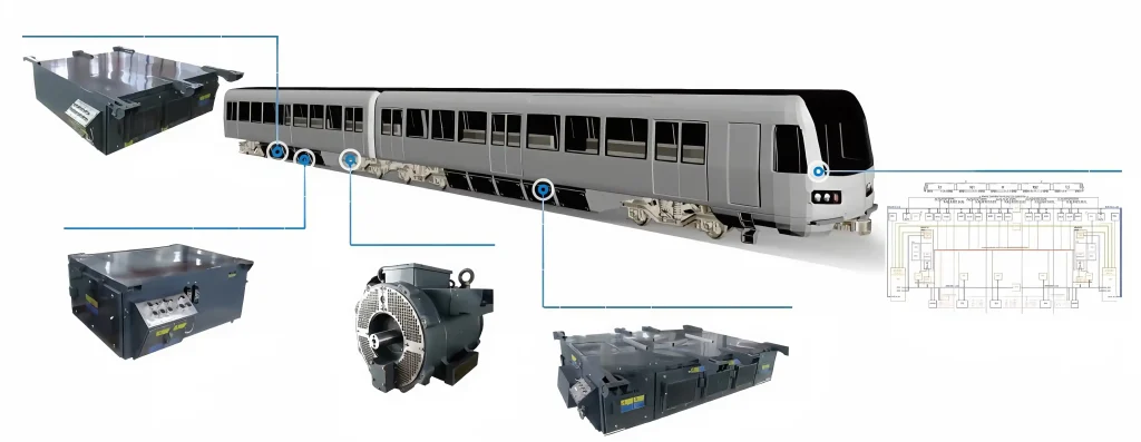
3. Braking system: the ultimate guarantee for safe operation
The braking system achieves precise speed control through a multi-stage braking mode, and its technical configuration includes:
Braking control unit (BCU): 32-bit microprocessor, sampling period ≤10ms, supports electric-air hybrid braking algorithm, braking force distribution error ≤3%. With anti-skid protection, load compensation, and fault diagnosis functions, response time is ≤1.5 seconds.
Basic braking device: The diameter of the disc brake unit is 640mm, the thickness is 110mm, and the heat capacity is ≥ 12 MJ; the electromagnetic suction force of the magnetic rail brake unit is ≥12kN, and the response time is ≤200ms.
Braking mode: Common braking deceleration is 1.0-1.2m/s², emergency braking deceleration is ≥1.3m/s², and the braking pressure is maintained at 3.0±0.2bar. The parking brake energy storage spring capacity meets the parking requirements of 30‰ slopes.
Redundant design: The braking system adopts a dual-channel redundant architecture. When a single channel fails, it can still guarantee more than 80% of the braking force output, and the braking distance increase rate is ≤15%.
4. TCMS system: the nerve center of intelligent control
The TCMS system realizes full train status monitoring and collaborative control through a distributed control architecture. Its technical configuration includes:
Network architecture: built based on the TCN standard, the WTB bus transmission rate is 1Mbps, the MVB bus transmission rate is 1.5Mbps, supports 1024 device access, and the data refresh cycle is ≤100ms.
Control unit: The central control unit (CCU) adopts a dual-machine hot standby redundant design, and the vehicle control unit (VCU) is equipped with a VxWorks real-time operating system, supporting MVB, Ethernet, and RS-485 multi-protocol communications.
Intelligent diagnosis: Integrated PHM module, through 2000+ sensors to achieve fault prediction accuracy ≥85%, support remote data upload and expert system analysis, maintenance suggestion generation time ≤5min.
Unmanned driving integration: Deep coupling with the CBTC signal system to achieve automatic train wake-up, sleep, in and out of the warehouse, and main line operation, positioning accuracy ±5cm, stop accuracy ±25cm.
5. System collaboration and performance optimization
The four major systems realize data interaction and logical linkage through TCMS:
The traction system adjusts the traction torque according to the load signal calculated by TCMS, and the braking system matches the braking force according to the speed command of TCMS.
The bogie vibration data is fed back to the traction system through TCMS to optimize the motor torque output to suppress wheel-rail impact.
When the braking system fails, TCMS automatically triggers the traction system safety braking mode to ensure that the train stops within the specified distance.
This coordination mechanism enables subway vehicles to maintain an average acceleration of 0.83m/s² and an emergency braking deceleration of ≤1.0m/s² under conditions of a passenger capacity of 310 people per vehicle and a maximum operating speed of 80km/h, fully reflecting the technological advancement of modern urban rail transit.