Scan the WeChat code to contact us
Scan the WeChat code to contact us
Feel free to send us a email and we will reply to you as soon as possible.
Creating the future with heart and soul
——Hardcore popular science from structure to operation
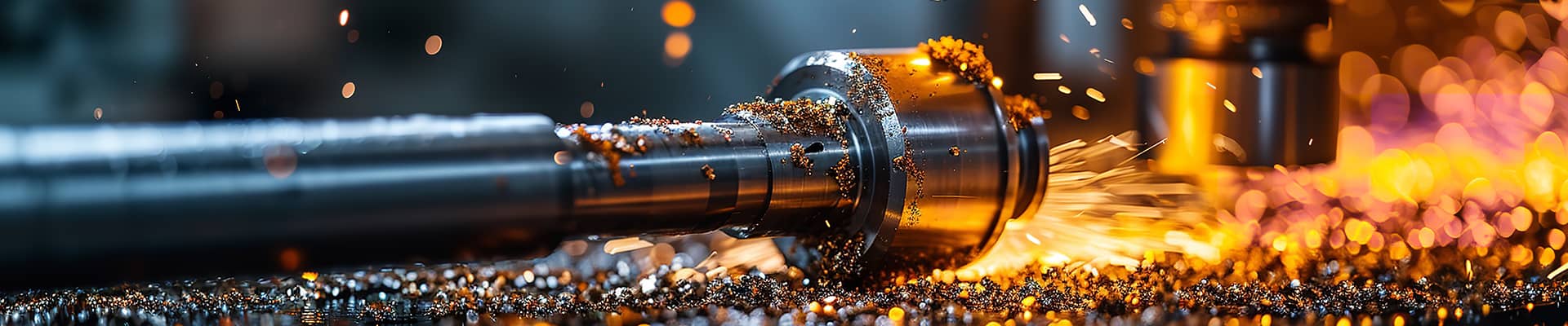
In the steel-cast rail network, EMUs are speeding at a speed of 300 kilometers per hour, and heavy-load mine trains are slowly climbing the slope with hundreds of tons of ore. The core component that connects all of this is the seemingly inconspicuous but lifeline coupler. It does not have the roar of the engine, nor the dazzling of the intelligent system, but with pure mechanical power, it silently completes key tasks such as train formation, traction transmission, and impact buffering. This article will unveil the mystery of this industrial miracle from the structural design, working principle, and usage of the coupler.
1. The “steel skeleton” of the coupler: structural disassembly
The design of the train coupler is like a precise mechanical Lego, and each component has a specific mission. Taking the universal coupler of the EMU (mine car) as an example, its core structure can be decomposed into five modules:
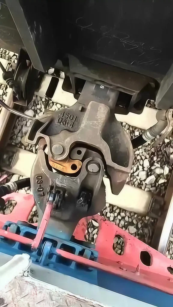
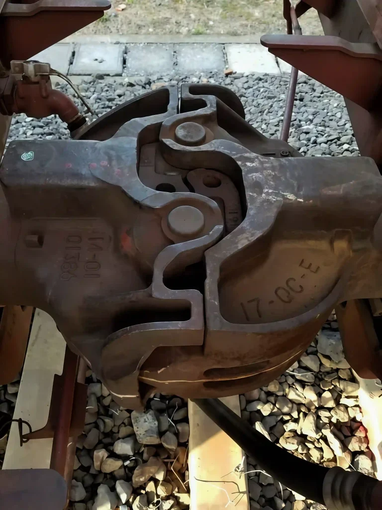
Coupler body: the “teeth” of the mechanical bite
Coupler tongue: shaped like the fangs of a beast, it is the part that is in direct contact when connecting. The opening angle of the mining coupler tongue is usually expanded to 110° (about 90° for the railway type) to achieve “blind connection” in dusty and low-visibility environments in mining areas.
Coupler cavity: The interior adopts a conical design. The convex cone of the coupler tongue and the concave cone of the hook cavity are engaged at an inclination angle of 3°-5°, and gravity and friction are used to form a self-locking force to ensure that no additional power is required after connection.
Hook tail frame: The thickness of the train coupler tail frame is about 50mm, and the mining-type is thickened to 80mm. The surface chrome plating layer is ≥80μm, which can withstand continuous impact of open-pit mine gravel without deformation.
Buffer device: Shock-absorbing “muscle system”
Rubber buffer: It is composed of multiple layers of rubber and steel plates, which absorb longitudinal impact force through elastic deformation and are suitable for daily marshaling operations of EMUs (impact frequency ≤5 times/day).
Hydraulic buffer (optional for mining): filled with high-viscosity hydraulic oil, the impact energy is converted into heat energy through piston movement, and can cope with ≥200 violent impacts per shift in the mining area (such as ore transportation after blasting).
Locking mechanism: the “nerve center” of safety
Three-level locking structure:
Main hook tongue: The first bite when hooking bears 80% of the traction force.
Anti-unhooking tongue: secondary protection is formed behind the main hook tongue to prevent unhooking caused by longitudinal impact.
Mechanical lock pin: rotate 90° after manual insertion to lock the hook tongue and hook cavity to ensure a hooking success rate of ≥99.5%.
Mining safety upgrade: the hook tail frame is equipped with an anti-unhooking baffle, and the hook tongue pin hole is built-in with a double-row needle bearing to reduce the wear of the hooking and prevent accidental unlocking.
Air duct and electrical interface (railway type)
BP pipe (brake pipe): transmits train braking instructions, with a pressure range of 0.6-1.0MPa and a leakage rate of ≤0.1L/min, to ensure the synchronization of braking of the entire train.
Electrical module: 12-core/24V DC interface, supports door control and lighting signal transmission, protection level IP65 (dustproof and waterproof).
Simplified design for mining: no electrical interface by default, optional explosion-proof cable connector (Ex d IIC T6), adapted to underground explosion-proof requirements.
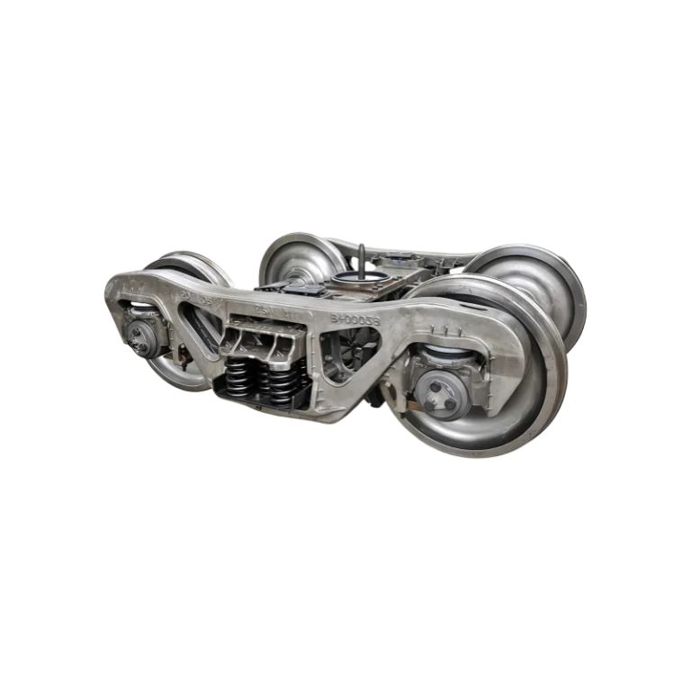
Bogie connection assembly
Hook pin: a solid steel column with a diameter of about 120mm, fixed to the bogie by bolts, and capable of withstanding the maximum longitudinal traction (2500kN for railway type and 4000kN for mining type).
Adjustment shims: The mining type is equipped with a replaceable shim set to adapt to different track gauges (1435-2000mm) and hook heights (400-600mm).
2. The “mechanical language” of the coupler: analysis of the mode of action
The operation of the coupler is like a precise mechanical dance, which realizes train marshaling and safe operation through physical principles:
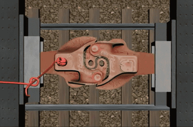
The coupling process: from “encounter” to “bite”
Railway coupling:
The two couplers approach at a speed of ≤5km/h, and the convex cone of the hook tongue and the concave cone of the hook cavity are initially in contact.
The hook tongue rotates under the action of gravity, and the convex cone slides into the concave cone to form a primary lock.
The locking pin is manually inserted and rotated 90° to trigger the anti-unhooking hook tongue lock and complete the third-level lock.
The air duct is automatically docked, and the electrical module is connected through contacts. The whole process is ≤15 seconds/section.
Mining coupling:
At a slope of ±20°, the opening angle of the hook tongue is expanded to 110°, allowing ±50mm vertical deviation.
The mental hook body width is increased by 30%, and the ability to resist lateral impact is increased by 2 times, which is suitable for the complex terrain of the mining area.
The hydraulic buffer is pre-filled with oil, and the coupling absorbs the impact energy instantly to avoid damage to the hook body.
Traction transmission: a “relay race” of force
When the train starts, the hook body transmits the traction force to the bogie through the hook tail pin and then converts it into track friction through the wheelset.
The mining-type hook body adopts the “wedge-shaped reinforcement rib” design. When the traction force is ≥350 tons, the stress distribution uniformity is improved by 40%, preventing the hook body from cracking.
Impact buffer: the “tamer” of energy
Braking shock: The rubber buffer is compressed and deformed to absorb the longitudinal energy generated when the train brakes (the energy absorption rate of the railway type is ≥75%).
Mining blasting shock: The hydraulic buffer piston moves, converting the impact energy into hydraulic oil heat energy, and cooperates with the hook body ceramic coating (hardness ≥9H) to resist the impact of gravel.
Unhooking operation: precise “mechanical separation”
Railway type: manually pull out the lock pin, the hook tongue automatically rotates and disengages under the action of the spring force, and the unhooking time is ≤10 seconds/section.
Mining type: equipped with an unhooking cylinder (optional), which pushes the hook tongue to unlock through compressed air, adapting to the scene of open-pit mines without manual operation.
3. The “practical manual” of the coupler: a complete guide to how to use it
From EMUs to heavy-duty mining trains, the operation of couplers must follow strict specifications:
Inspection before coupling: details determine safety
Hook body inspection: confirm that there are no cracks in the hook tongue, no foreign matter in the hook cavity, and no peeling of the ceramic coating of the mining hook body.
Buffer test: The compression stroke of the railway-type rubber buffer is ≥50mm, and there is no oil leakage in the mining hydraulic buffer.
Air duct and electrical: The railway type needs to test the BP pipe pressure (0.8±0.1MPa) and the insulation resistance of the electrical module (≥100MΩ).
Coupling operation: Execute in different scenarios
EMU coupling:
The two cars approach at a speed of ≤3km/h, and the coupling operator visually confirms the alignment of the hook tongue on the side of the car.
At the moment of contact between the hook tongue, the coupling operator applies a torque of ≤60N·m to rotate the lock pin, triggering the third-level locking.
After coupling, the wind pressure gauge is used to confirm that the BP pipe pressure is stable, and the indicator light of the electrical module is on.
Heavy-load coupling for mining:
On a track with a slope of ≤20°, the mine car approaches at a speed of ≤2km/h, and a vertical deviation of ±50mm is allowed.
After the locomotive coupler tongue contacts, the hydraulic buffer automatically adjusts to the pre-charge pressure without manual intervention.
When the coupling is completed, the gap between the anti-slip baffle of the hook tail frame and the mental hook body is ≤2mm to ensure impact resistance.
Monitoring during operation: Take precautions before they happen
Railway type monitoring: Check the wear of the hook tongue every 500 kilometers (≤3mm), and ensure there is no air leakage in the air duct joint.
Mining type monitoring: Check the thickness of the ceramic coating on the locomotive coupler body (≥50μm) every shift, and the oil temperature of the hydraulic buffer is ≤80℃.
Unhooking and maintenance: Standardization extends service life
Unhooking process:
Railway type: First, close the BP pipe shut-off valve, then pull out the lock pin to avoid damage to the hook tongue due to pressure unhooking.
Mining type: If a cylinder is used to unhook, it is necessary to confirm that the compressed air pressure is ≥0.6MPa to prevent unhooking failure.
Maintenance cycle:
Railway type hook body: replace the hook tongue pin grease every 30,000 kilometers or 1 year.
Mining type hook body: check the thickness of the chrome plating layer of the locomotive coupler tail frame every 2,000 hours or 6 months (≥70μm).
4. The “evolution code” of the hook: from tradition to the future
Although the current rail car coupler is mainly mechanical, the industry is exploring the following upgrade directions:
Lightweight materials: Titanium mental hook body (density 4.5g/cm³, tensile strength ≥1100MPa) can reduce weight by 30%, suitable for high-speed EMUs.
Intelligent monitoring: fiber optic sensors are embedded inside the hook body to monitor stress and crack extension in real time, and the early warning cycle is advanced to 200 hours before the failure.
Unmanned coupling: through laser radar and machine vision, the fully automatic coupling of mining cars in dusty environments is realized, with an error of ≤5mm.
Conclusion
The coupler, the “invisible bond” of the industrial age, connects the steel behemoth with pure mechanical wisdom. From the elegant marshaling of EMUs to the rough impact of heavy-load mining trains, it has always been the core guarantee of train safety and efficiency. Understanding the structure, function and operation of couplers is not only a compulsory course for engineers, but also a tribute to the precise collaboration of industrial civilization.